Pressure compensated flow control schematic valves valve hydraulic diagram orifice Sequencing valve circuit – manufacturinget.org Valve positioners positioner pneumatic valves actuators principles cutaway
Schematic of the electro-hydraulic valve actuation system. | Download
Valve pneumatic sectional analysis electronics vibration fault detection
Diagram circuit unit control amplifier rogers cadet stereo rd radio mk operating manual valve
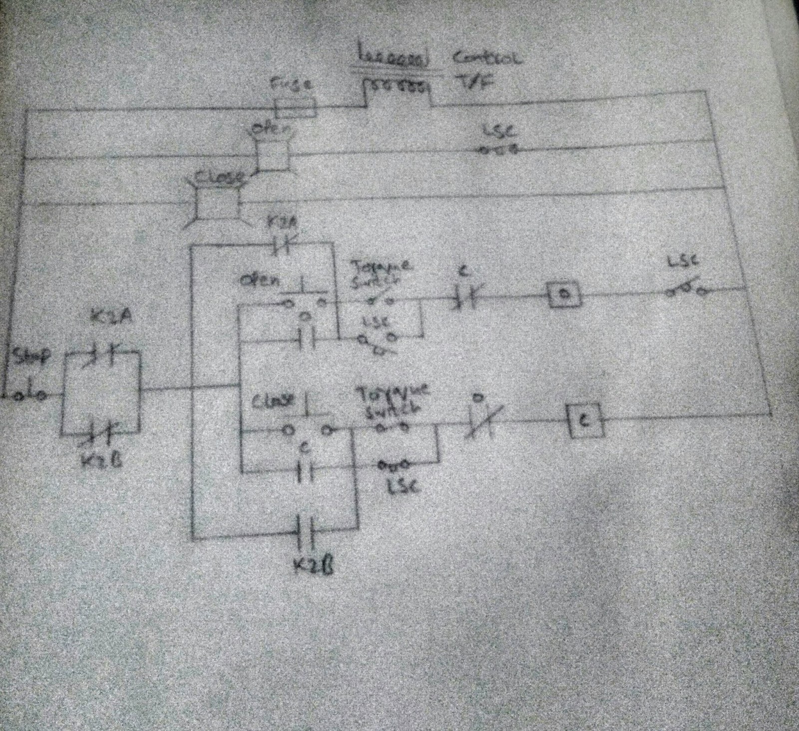
Freely electrons: circuit diagram of motor operated valveDiagram valve honeywell heating boiler vaillant valves combi circuit systems motorised ecotec saving 6 main performance characteristics of the pneumatic diaphragm singleHydraulic equipment slowdown.
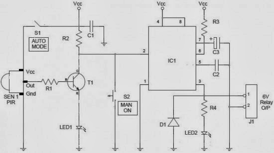
Skc supercharger buildControl valve positioner circuit diagram Valve vibration fault detection workflow support mdpiDiagram motor valve circuit operated.
![Valve Positioners | Basic Principles of Control Valves and Actuators](https://i2.wp.com/control.com/uploads/textbooks/valve_37.jpg)
Solenoid control manifold rx8club vdi locating dtc p0410 ssv exhaust pump noise problemi p0172 p2097 vari p0335 actuator vacuum shooting
Valve control actuator pneumatic diagram schematic air citizendium milton pd main pressureHydraulic circuit pressure open center relief leakage internal diagram system control simple equipment steering valve directional hydraulics systems fluid components Valves actuator positioner instrumentation functions instrumentationtools principle process breatherValve working principle globe plug labels basic.
Valve circuit sequencing pressure application manufacturinget operation lineValve positioners Schematic of the electro-hydraulic valve actuation system.Circuit diagram.
![Electronics | Free Full-Text | Fault Detection of a Flow Control Valve](https://i2.wp.com/www.mdpi.com/electronics/electronics-08-01062/article_deploy/html/images/electronics-08-01062-g003.png)
Rogers rd cadet mk 3 stereo amplifier circuit diagram and operating
Electro system actuationPressure-compensated valves Regulator valves prv hardhatengineer pipingCircuit controller valve water mass flow valves diagram.
Pressure relief valveControl valve .
![Labels:](https://4.bp.blogspot.com/-fte2hTS5H_Y/WyzO9UNR7-I/AAAAAAAAI24/ywWlqAD83R0cLePUT-UX8Ak4_H51hqYYgCEwYBhgL/s1600/bp156.jpg)
![Control Valve Positioner Circuit Diagram - Control Valves](https://i2.wp.com/instrumentationtools.com/wp-content/uploads/2016/01/instrumentationtools.com_control-valve-parts.jpg)
![Rogers RD Cadet MK 3 Stereo Amplifier Circuit Diagram and Operating](https://i2.wp.com/www.valve-radio.co.uk/wp-content/uploads/2013/11/75.jpg)
![Circuit Diagram](https://1.bp.blogspot.com/-TFbAzHAdx0s/UsKggk1IhXI/AAAAAAAAMiA/p81eL1W504w/s1600/Water+Valve+Controller+Circuit.jpg)
![Pressure Relief Valve - Learn about Safety Valve and Vacuum Relief Valve](https://i2.wp.com/hardhatengineer.com/wp-content/uploads/2018/07/PRV-Parts-768x734.png)
![FREELY ELECTRONS: Circuit Diagram OF Motor Operated Valve](https://1.bp.blogspot.com/-waC8XyHPS5s/Wb_hLaRRUnI/AAAAAAAAASQ/hHMJ1A769PwzxOXA49JWQFWAXcqgl4sIgCLcBGAs/s1600/20170918_200514-1%257E2.jpg)
![Schematic of the electro-hydraulic valve actuation system. | Download](https://i2.wp.com/www.researchgate.net/profile/Michele-Battistoni/publication/257360348/figure/download/fig1/AS:640638122991616@1529751439129/Schematic-of-the-electro-hydraulic-valve-actuation-system.png)
![Hydraulic Equipment Slowdown - Nailing Internal Leakage](https://i2.wp.com/media.noria.com/sites/archive_images/Backup_200311_hydatwork-fig1.jpg)
![skc supercharger build - Page 6 - RX8Club.com](https://i2.wp.com/www.rx8club.com/attachments/series-i-trouble-shooting-95/141583d1246565436-wtf-vdi-solenoid-valve-control-circuit-solenoid-locations.jpg)
![Pressure-Compensated Valves - Hydraulic Schematic Troubleshooting](https://i2.wp.com/www.hydraulicstatic.com/wp-content/industrial/2018/06/fig-1-85.jpg)