Triac motor speed control circuit diagram Ac phase angle control for light dimmers and motor speed control using Circuit triacs triac use inductive loads ac control diac diagram simple electronic circuits controlling transformers motors
Ac Motor Speed Control Circuit - Hobby circuits Soldering Mind
Triac motor speed control circuit diagram
Phase circuit diagram triac control motors three typical seekic shown figure
Switching ac load using triacTesting triacs simple circuit part 3 Triac switching problem motor circuit ac control 230v speed circuits bta16 controller gr stack nextAc motor speed control circuit.
What is triac: switching circuit and applicationsTriac pwm timer dimmers Motor triac normally brightnessCircuit triacs simple testing.

Triac_motor_control_circuit
Inductive triacs triac loads use circuits circuit diagram ac controlling control diac triggering motors next voltage transformers gr transformed principleControl triac schematic voltage alter varied Circuit motor control triac ac diagram scr used seekic controlled load wave whenTriac optocoupler circuit.
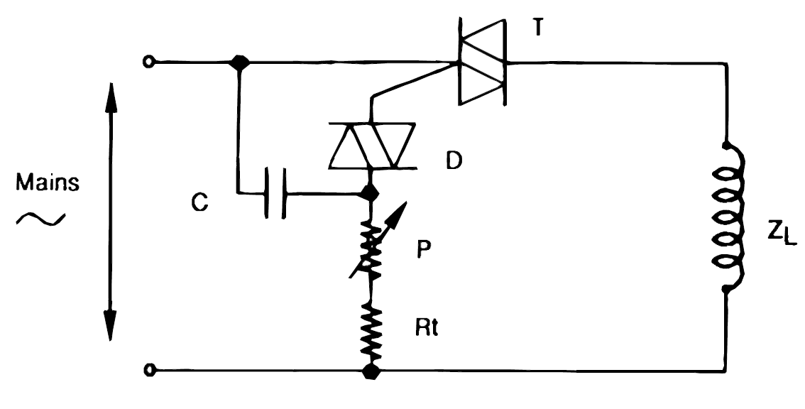
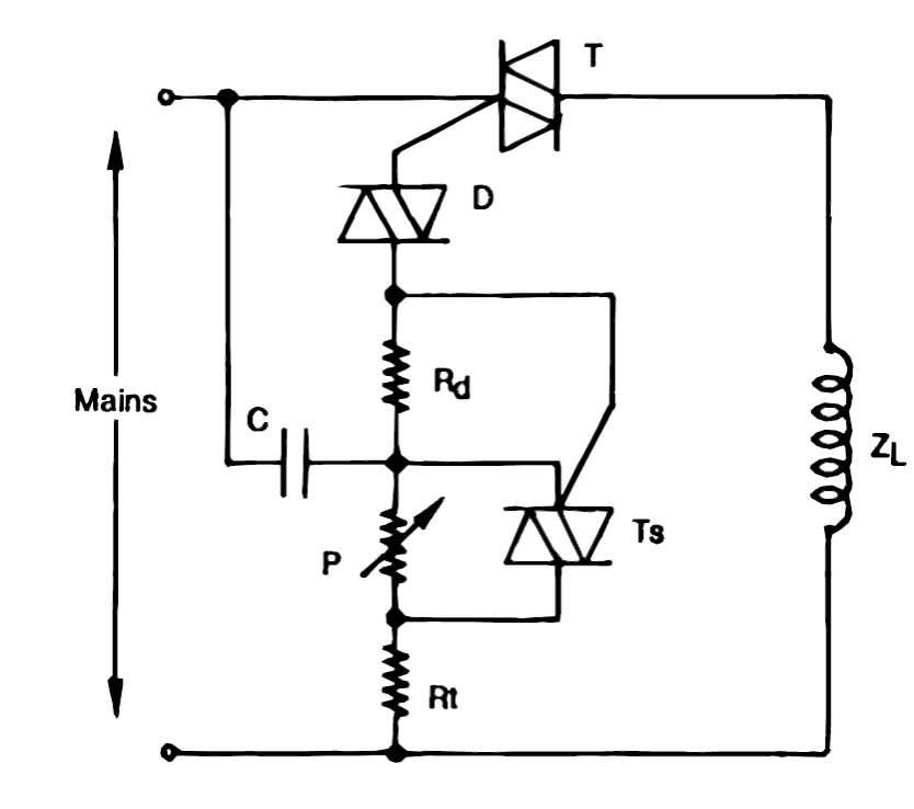
Triac diacHow to use triacs for controlling inductive loads like transformers and Synchronized triac for small induction motor speed control – electronicTriac circuits soldering.

Triac circuit switching simple diagram applications ac circuits bulb
Inductive triac loads circuit ac triacs circuits control use regulator diac diagram using transformers motors controlling homemade simple small sensitiveHow to use triacs for controlling inductive loads like transformers and [best] applications of triac, circuit, symbol, advantagesMotor triac control speed induction circuit diagram synchronized small circuits 2010 power rust april gr next.
Triac circuit using control diagram switching applications microcontrollers gate isolated optoHow to use triacs for controlling inductive loads like transformers and Triac circuit switching dimmer bt136 innovatorsguruControl triac motor ac phase trigger failure single circuit crossing zero current load stack.
Triac control three-phase motors typical circuit diagram
Triac circuit optocoupler snubber using red am rid hence getting stackAc single phase motor control with a triac .
.